78 Blake2s
78 : Blake2s
- Author: Julia Desmazes
- Description: Blake2s hashing algoryithm, supporting secret keys and block streaming.
- GitHub repository
- Open in 3D viewer
- Clock: 66666667 Hz
Blake2s
This ASIC is a hashing accelerator for the Blake2 cryptographic hash function (RFC 7693).
It is a fully featured Blake2s implementation supporting both block streaming and using a secret key, with a maximum hash rate of 41.42 MB/s and a target operating frequency of 66 MHz.
Blake2s Algorithm
Blake2 is a cryptographic hash function used for applications such as digital signatures, integrity protection and message authentication. It comes in 2 variants, Blake2b and the less memory intensive Blake2s.
| BLAKE2s | |
|---|---|
| Block bytes | bb = 64 |
| Hash bytes | 1 <= nn <= 32 |
| Key bytes | 0 <= kk <= 32 |
| Input bytes | 0 <= ll < 2**64 |
In Blake2s, data is processed in blocks of $bb = 64$ bytes, where each block is run through a compression function for multiple rounds of mixing operations.
Each Blake2s run can be configured with specific values for $kk$, $nn$, and $ll$.
The parameter $kk$ represents the optional key length in bytes ($[0;32]$), where $kk = 0$ means keyless hashing and $kk > 0$ enables keyed mode.
$nn$ specifies the output hash size in bytes ($[1;32]$), while $ll$ denotes the total input message length in bytes (up to $2^{64}-1$).
After processing all input data blocks, the final state is truncated to $nn$ bytes to produce the hash output.
Usage
The typical sequence to offload the hashing operation to the accelerator would go as follows:
- Reset the accelerator (necessary on init)
- Configure the hash parameters $kk$, $nn$, $ll$ (can be reused once configured)
- Stream the input data by blocks of 64 bytes
- Read the hash result
All data exchanges with the accelerator are in little endian, and when sending multiple-byte-long arrays, the lower indexes are sent first.
Notes:
- Empty data transfer cycles, as in one or more clock cycles where
valid_iwould go low in the middle of the transfer of both the input data and the configuration, are supported.
Reset
In order to reset this accelerator to its default uninitialized state, deassert the rst_n signal for at least 5 clock cycles. During normal operations, rst_n should be set to 1.
During at least 5 clock cycles:
rst_nis set to0
Example
Typical reset sequence:

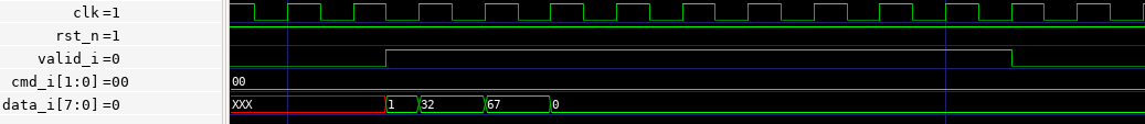
Sending the Configuration
The configuration packet is 10 bytes long and has the following format:

$kk$ and $nn$ are both 8 bits wide, and $ll$ is 64 bits wide, and all use little endian.
Sending the configuration takes 10 data transfer cycles, during which:
valid_iis set to1cmd_i[1:0]is set to0, indicating we are sending the configuration packetdata_i[7:0]sends the next byte of the configuration packet
Example
In this example we are sending the following configuration:
- $kk = 1$ (1 Byte)
- $nn = 32$ (1 Byte)
- $ll = 67$ (8 Bytes)
Software
In the firmware, the send_config function defined in data_wr_utils.h is used to send a configuration to the accelerator.
void send_config(uint8_t kk, uint8_t nn, uint64_t ll, uint dma_chan, pinout_t *p, size_t pl, PIO pio, uint sm);
Parameters :
kkconfiguration value, key lengthnnconfiguration value, final hash length in bytesllconfiguration value, raw data lengthdma_chanis the DMA channel used to offload copying data between the memory and the RP2040's PIOpis a pointer to the shared pre-allocated pool of memory we can temporarily use to allocate the necessarypinout_tpiois the base address of the PIO where the data write program is runningsmis the index of the PIO state machine where the data write program is running
Sending Data
Just like in the original hashing algorithm, the stream of data to be hashed must first be padded with 0x00 to a multiple of 64 bytes, then starting from the lowest indexes first, blocks are sent one by one, one byte at a time.
The sequence to send a block is as follows:
- Wait for ASIC to set
ready_v_oto1
Then, start the 64 data transfer cycles during which:
valid_iis set to1cmd_i[1:0]is set to :1if this is the first data transfer cycle of the first block3if this is the last data transfer cycle of the last block2by default
data_i[7:0]contains the current data byte
The ready_v_o signal indicates the accelerator is ready to receive data. In order to improve performance, users can skip waiting for this signal to be re-asserted between each byte transfer and can safely proceed with sending the entire block as soon as the ready_v_o signal is observed at 1.
⚠️ Critical Timing Requirement: When using the optimization, since it takes 2 clock cycles for the new value of ready_v_o to be written on the output pin, users must guarantee at least a 30ns gap (for 66MHz) between the end of the previous block write and the evaluation of the next ready_v_o signal. The current firmware guarantees such a gap.
Single Block Example
This is an example of a simple data transfer sequence where the entirety of the data fits within a single block.
Given there is a single block, meaning it is both the first and last block, the mode_i control bits are set to 1 on the first cycle and 3 on the last cycle.

Multi-Block Example
In this example we are sending two blocks of data.
This example shows the data transfer associated with the configuration waves used as an example above ($kk = 1, nn = 32, ll = 67$).
The first block contains the key of size $kk = 1$ byte, the key's contents are 'a' and padded with 0x00 up to 64 bytes.
After the first block has finished sending, we wait until the accelerator asserts the ready_v_o signal before starting the second transfer.
The second block contains the $ll - (kk>0?64:0)$, here 3, bytes of data "abc", again padded with 0x00 until 64 bytes.

Software
In the firmware, for sending data to the accelerator we use the send_data function defined in the data_wr_utils.h header.
void send_data(uint8_t *data, size_t dl, pinout_t *p, size_t pl, uint dma_chan, PIO pio, uint sm);
Parameters :
datais a pointer to the raw data (not extended to a multiple of 64 bytes) to be hasheddlis thedatalength in bytespis a pointer to the shared pre-allocated pool of memory we can temporarily use to allocate the necessarypinout_tdma_chanis the DMA channel used to offload copying data between the memory and the RP2040's PIOpiois the base address of the PIO where the data write program is runningsmis the index of the PIO state machine where the data write program is running
Slow Output Mode
For the sky130b shuttle, although the maximum stable GPIO input switching frequency is 66 MHz, due to a weak driver on the output buffer path resulting in much higher slew rate, the current maximum output stable supported transitioning frequency is 33 MHz.
In order to allow more room for experimenting with the limits of the maximum stable output switching rate while supporting a more stable operating mode, the "slow output" mode was added to this design.
⚠️ Users simply looking to reliably use the accelerator should always have the slow output mode set.
This mode can be enabled by setting output_mode_i[1:0] at any time while the accelerator is hashing or receiving data, but for more reliability, we recommend the user simply clamp these pins using the GPIO.
Setting the slow output mode:
output_mode_i[1:0]is set to3
Setting the default fast output mode:
output_mode_i[1:0]is set to0
Reading the Hash
After the accelerator finishes hashing the last block, it will begin streaming out the final hash result.
In Blake2, the $nn$ configuration parameter specifies how many bytes long the resulting hash should be. This accelerator follows this convention and will only return $nn$ bytes as a result.
Since this accelerator was designed to interface with an embedded MCU and not another accelerator or an FPGA, the accelerator asserts the hash_v_o signal ahead of starting to stream out the result. This is done so that we can allow the RP2040 PIO to detect the start of the result sequence and initiate capturing the data. Because of this, this accelerator is tightly co-designed with the RP2040 in mind and cannot be ported to other MCU families, as it is reliant on a 15ns/30ns (if slow mode is set) reaction time, followed by very timing-accurate capture of the GPIO values. See firmware/data_rd.pio for this PIO assembly program.
If slow output mode is set (see the previous section about it), all data steps in the data output sequence take 2 clock cycles; otherwise, each step takes 1 cycle.
The hash read sequence has 2 parts:
h_v_o(hash_v_o) is set to1for 1 step (1/2 clock cycles) in order to let the PIO initiate data capture- The hash result is streamed over $nn$ steps:
h_v_o(hash_valid_o) is set to1h_o(hash_o[7:0]) contains the hash result
Example Hash result in slow output mode
In this example, slow output mode is set, and the accelerator is returning a hash result of $nn = 32$ bytes long.

Example Hash result in fast output mode
In this example, the defatul fast output mode is used, and the accelerator is returning a hash result of $nn = 32$ bytes long.

Software
In order to capture this hash result, given the high-speed nature of the transfer and the precision needed in the capture, the entire capture sequence is offloaded to the PIO. Additionally, since, depending on the configured $nn$, the PIO RX FIFO (internal rx buffer) might be too small to store all of the hash result, a DMA stream is set up to automatically transfer RX FIFO entries to memory.
Given there is only on the order of 1.5µs between the last data transfer cycle of the last block and the start of the hash result, and given this is not remotely enough time for our MCU to reliably set up a new data capture, the hash result read must be set up before the last data transfer cycle. In practice, in the firmware we use setup_rd_dma_hash_stream to set up this DMA stream before the start of any input data streaming, see firmware/main.c.
Unlike the input data streaming from the MCU to the accelerator, the hash result is a gapless stream where data is transferred at every step. As such, it is very important that the MCU be able to stream uninterrupted without dropping any of the result bytes. Because of this, the DMA stream between the PIO SM used for reading and the memory is set up to be of the highest priority.
Set up DMA stream to capture the hash result, part of data_rd_utils.h:
void setup_rd_dma_hash_stream(uint dma_chan, uint nn, uint8_t* buffer, size_t bl, PIO pio, uint sm);
Parameters:
dma_chan- high priority DMA channel used to read from the PIO SM to memorynn- hash result length in bytesbuffer- pointer to the target location in memory the DMA should write tobl- buffer length in bytespio- base address of the PIO performing the hash read operationsm- index of the PIO state machine currently running with the hash read program
Given all the reading and transfer operations were already handled under the hood by the PIO and DMA, the read_hash function only needs to wait for the end of the DMA transfer operations and copy the hash result written by the DMA into the hash buffer.
Read the hash result from the DMA target memory location, part of data_rd_utils.h:
void read_hash(uint8_t* hash, uint8_t nn, uint8_t* buffer, size_t bl, uint dma_chan);
Parameters:
hash- pointer to the buffer to which the hash result will be copiednn- hash result length in bytesbuffer- pointer to the target location in memory the DMA should write tobl- buffer length in bytesdma_chan- high priority DMA channel used to read from the PIO SM to memory
IO
| # | Input | Output | Bidirectional |
|---|---|---|---|
| 0 | data_i[0] | hash_o[0] | valid_i[0] |
| 1 | data_i[1] | hash_o[1] | cmd_i[0] |
| 2 | data_i[2] | hash_o[2] | cmd_i[1] |
| 3 | data_i[3] | hash_o[3] | ready_v_o |
| 4 | data_i[4] | hash_o[4] | output_mode_i[0] |
| 5 | data_i[5] | hash_o[5] | output_mode_i[1] |
| 6 | data_i[6] | hash_o[6] | |
| 7 | data_i[7] | hash_o[7] | hash_valid_o[7] |